Your browser is out-of-date!
For a richer surfing experience on our website, please update your browser. Update my browser now!
For a richer surfing experience on our website, please update your browser. Update my browser now!
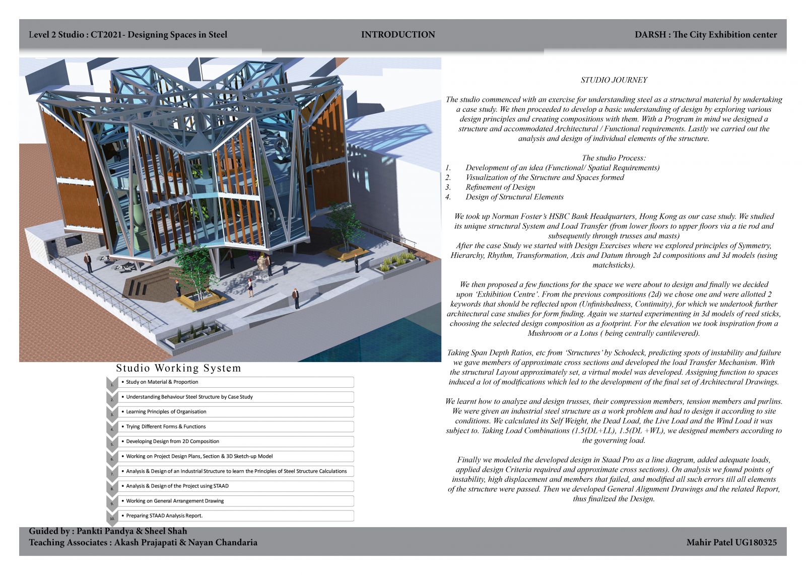
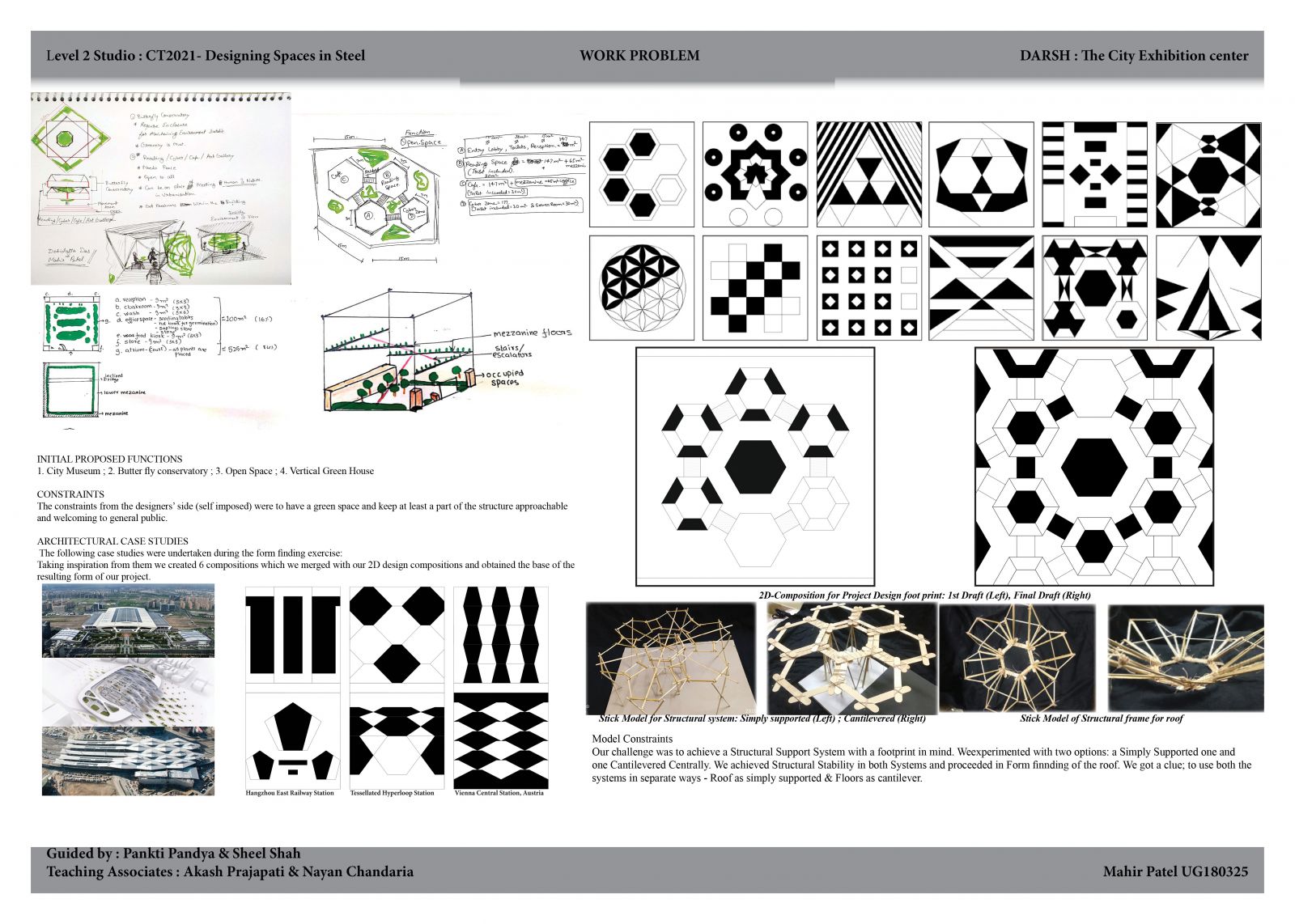
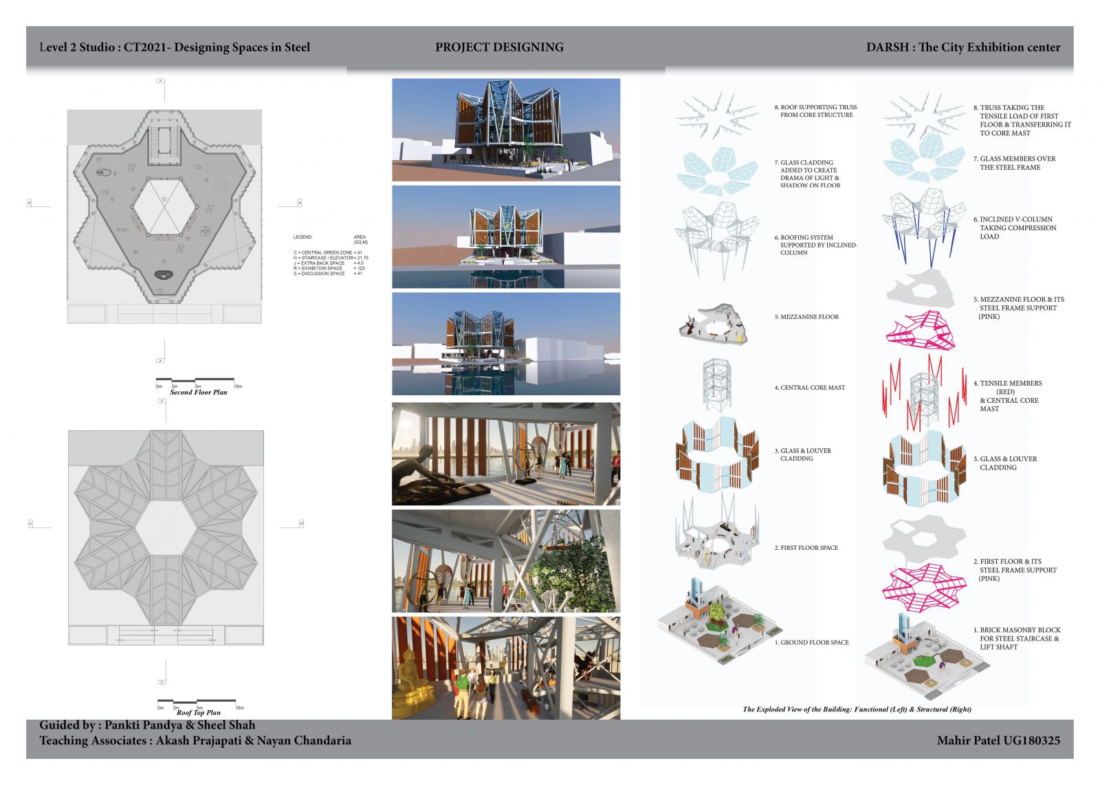
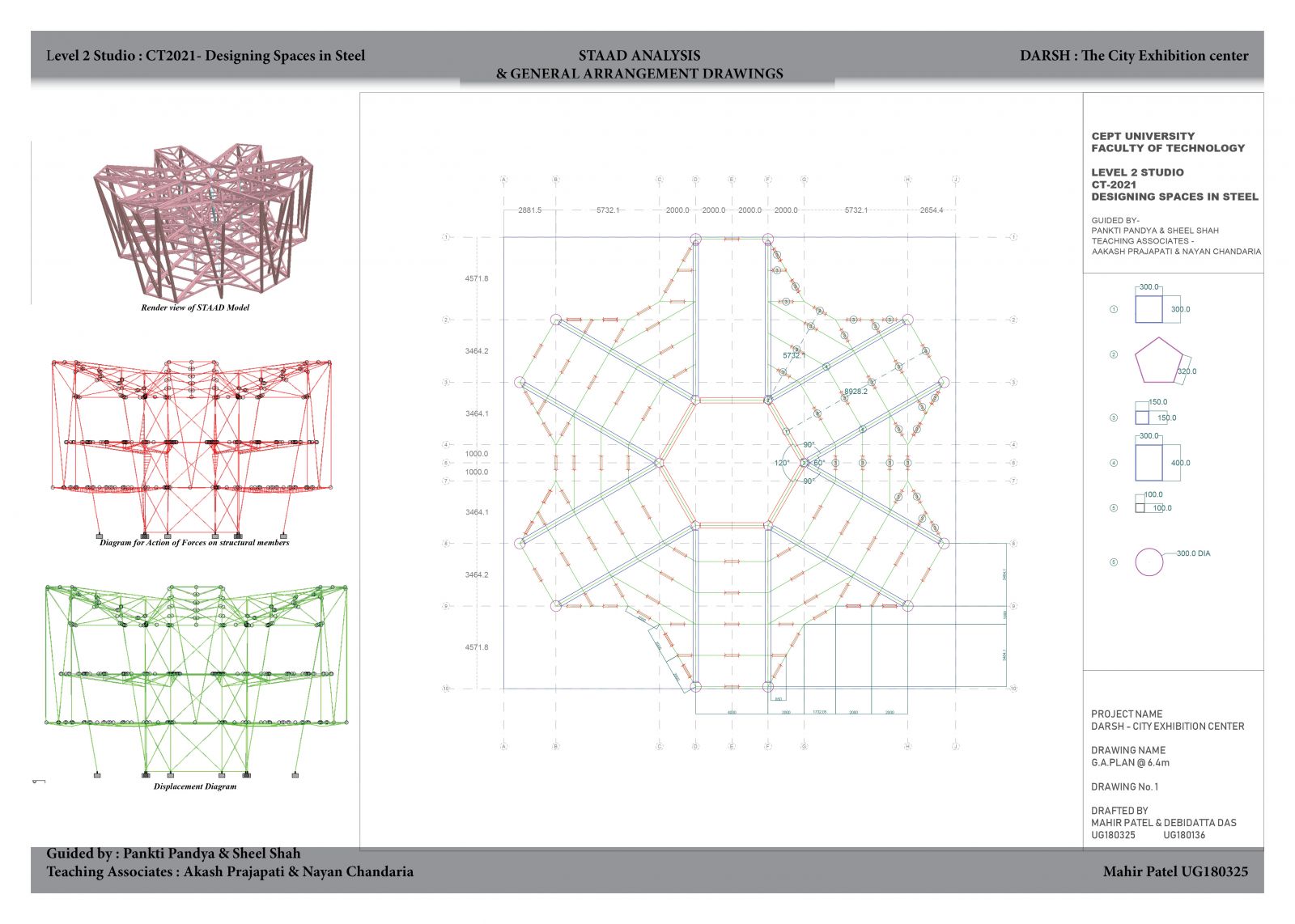
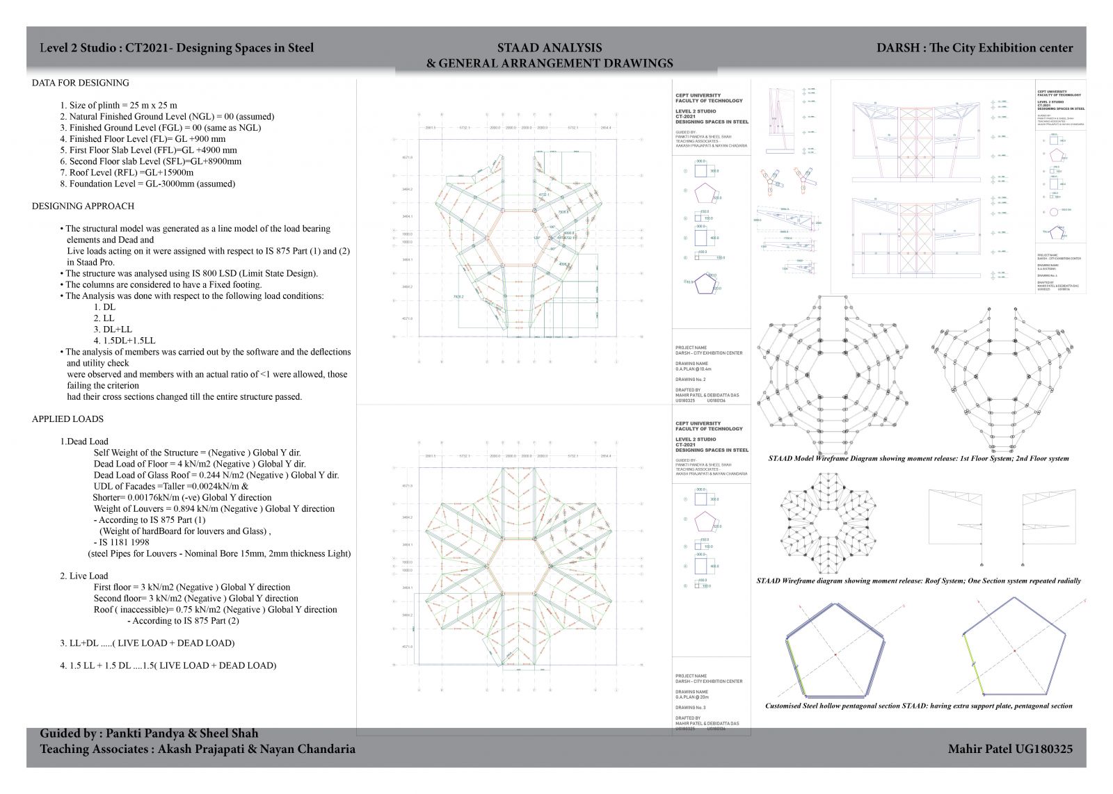
DARSH (Sanskrit- to display) is a city exhibition centre. The design is done on the principles of Symmetry, Hierarchy, Continuity and Unfinishedness. The upper storeys of the structure are cantilevered from the central core that features as our green space to the structure. The form has been inspired from a lotus / mushroom, that is radially cantilevered. The structure is designed such that it is fully accessible to everyone. The plinth is accessible by ramps . The two depressions in the plinth can be used as informal meeting spaces as well as amphitheatres for discussions for visitors and can also seat guests on occasions. The rear part of the ground floor houses the office, a storage facility, public restrooms and a café. A masonry structure houses the stairs and lift shafts, which would lead us to the first-floor that is, the exhibition space. Overall, it is a structure welcoming everyone.The first floor is formed by merging 6 individual hexagons around a core housing the green space which creates a divide enabling more exhibits. Proceeding, towards the mezzanine, some spaces of the lower floor is uncovered creating double heighted spaces on the first floor and giving an unfinished appearance. The roof form of which is inspired from a flower. It is inclined to give a sense of hierarchy and create spaces with an aura of grandeur. The roof consists of a steel grid which supports the cladding of glass and wooden louvres. The steel grid is supported by trusses branching from the masts. The structure is clad partially in glass and the rest in louvres for increased interactivity also to further develop on the unfinished look.The structural model was generated as a line model of the load bearing elements and Dead and Live loads acting on it were assigned with respect to IS 875 Part (1) and (2) in Staad Pro. • The structure was analysed using IS 800 LSD (Limit State Design). • The columns are considered to have a Fixed footing. • The Analysis was done with respect to the following load conditions: 1. DL 2. LL 3. DL+LL 4. 1.5DL+1.5LL • The analysis of members was carried out by the software and the deflections and utility check were observed and members with an actual ratio of < 1 were allowed, those failing the criterion had their cross sections changed till the entire structure passed. Link to Studio Portfolio Link to Structural Report
View Additional Work