Vrinda Khandelwal

CFP004

u21293

Foundation Studio (II), within the CEPT Foundation Programme continues to build upon the skills acquired during the first semester, adding abilities to use digital media in representation; to make models; to understand the assembly of built form through its building elements, materials and structures; to be able to draft architectural and topographical drawings: and eventually leads to bringing the skills and abilities together to tackle a design problem.

View Additional Work
Report Content

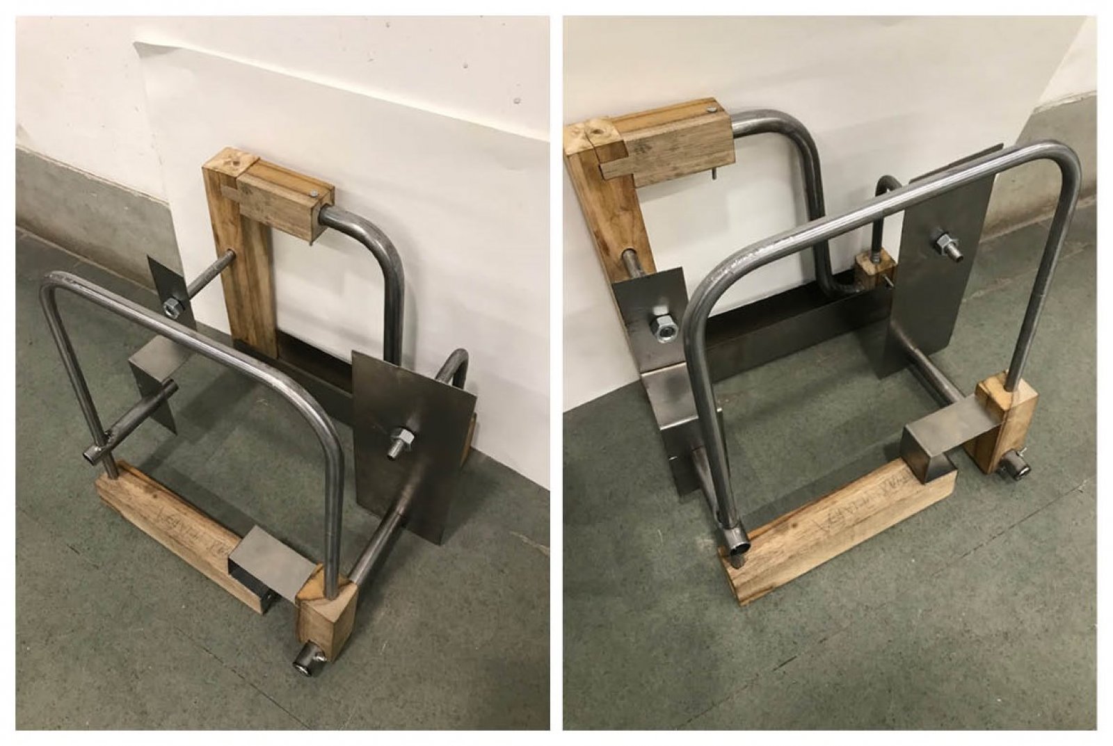
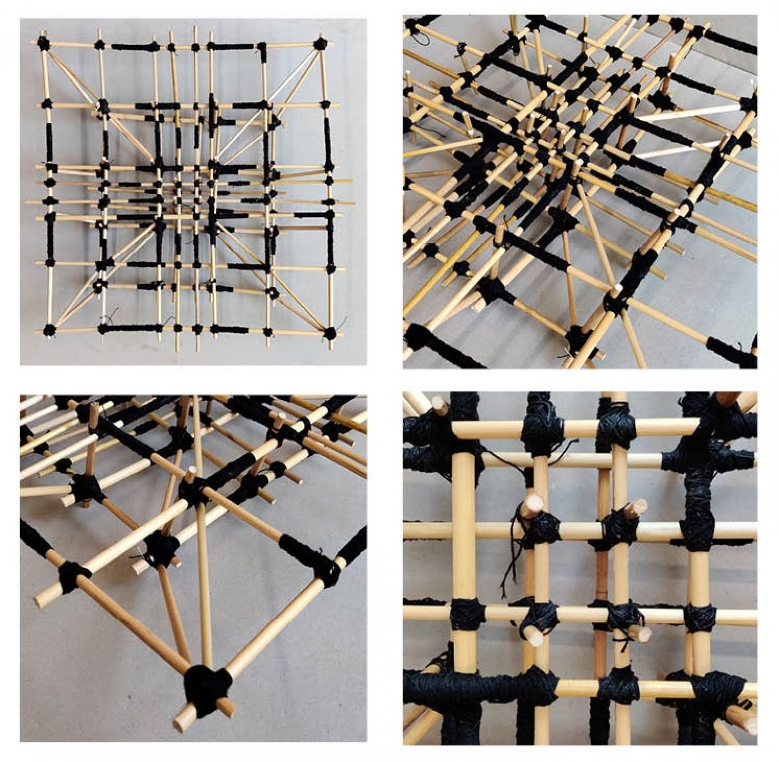
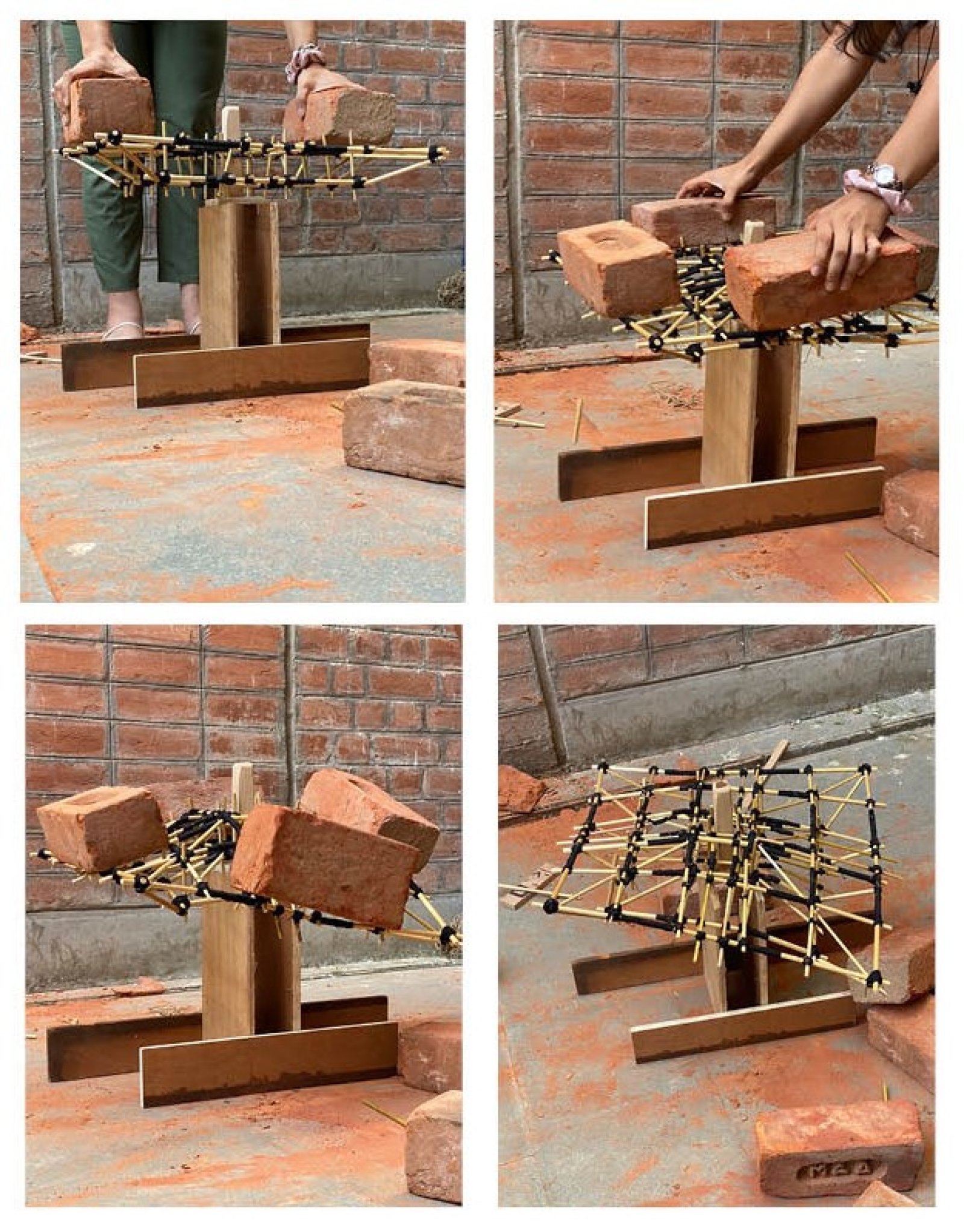
After studying the material and how a structure can hold the external weight, we designed the structure of a cantilever plate with the most suitable joineries and junctions. (S12-Making & Testing Structures)

The plate was designed to hold a weight ranging from 8-10 kilograms. The structure has been tested to check how the structure holds and distributes the weight along with the joineries and junctions. (S12-Making & Testing Structures)

This is an assemblage made of wood, metal rod, metal pipe, and metal plate. Our aim was to make an assemblage with all the possible combinations to learn about the materials as much as possible for example wood to wood joinery, metal rod to metal pipe joinery, etc. We use screws, bolts, and wooden pipes to join them. (S13-Joining Elements)

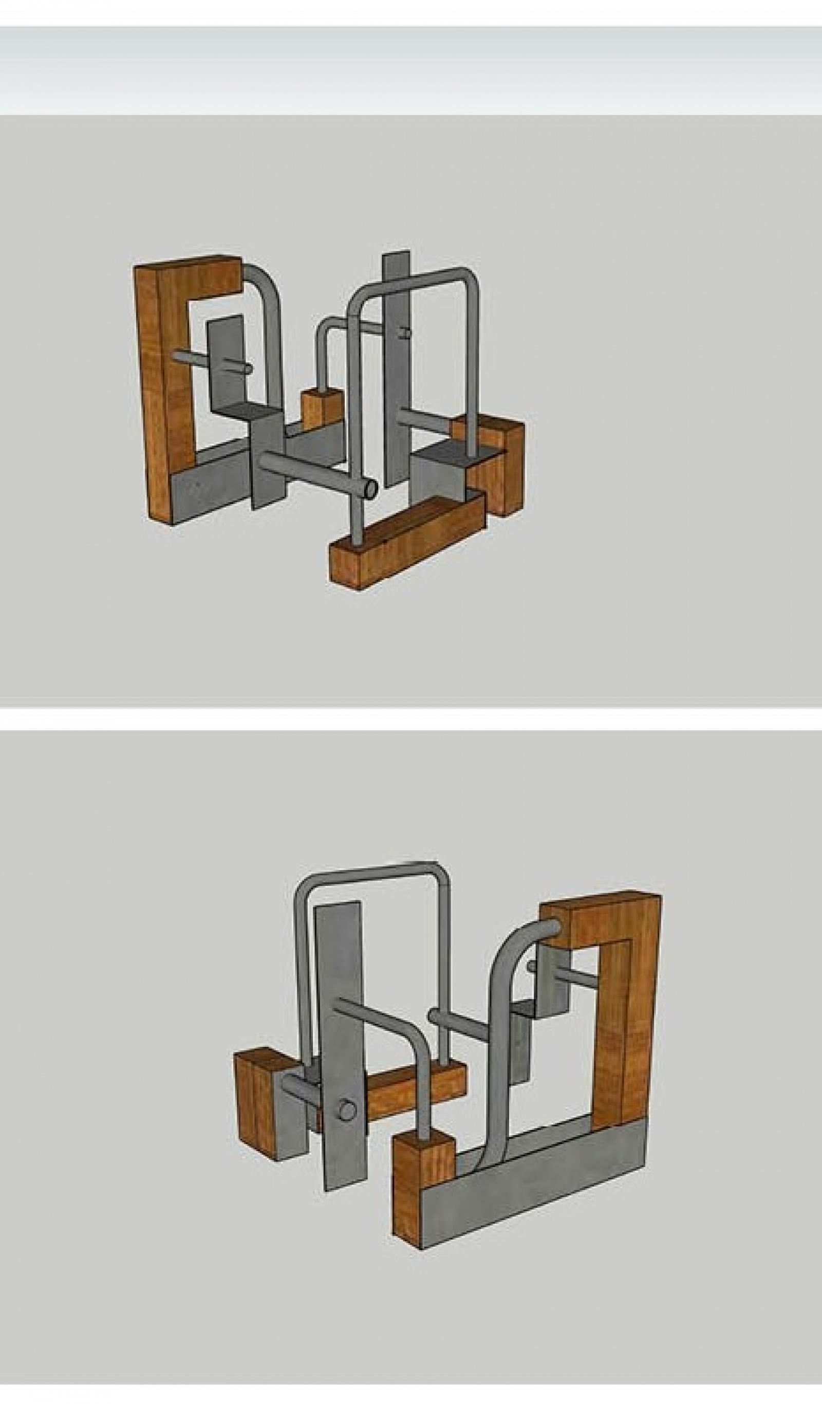
This is a model designed in SketchUp which is a dummy of our assemblage. This was made just to get the idea of how our model would look after completion. (S13-Joining Elements)

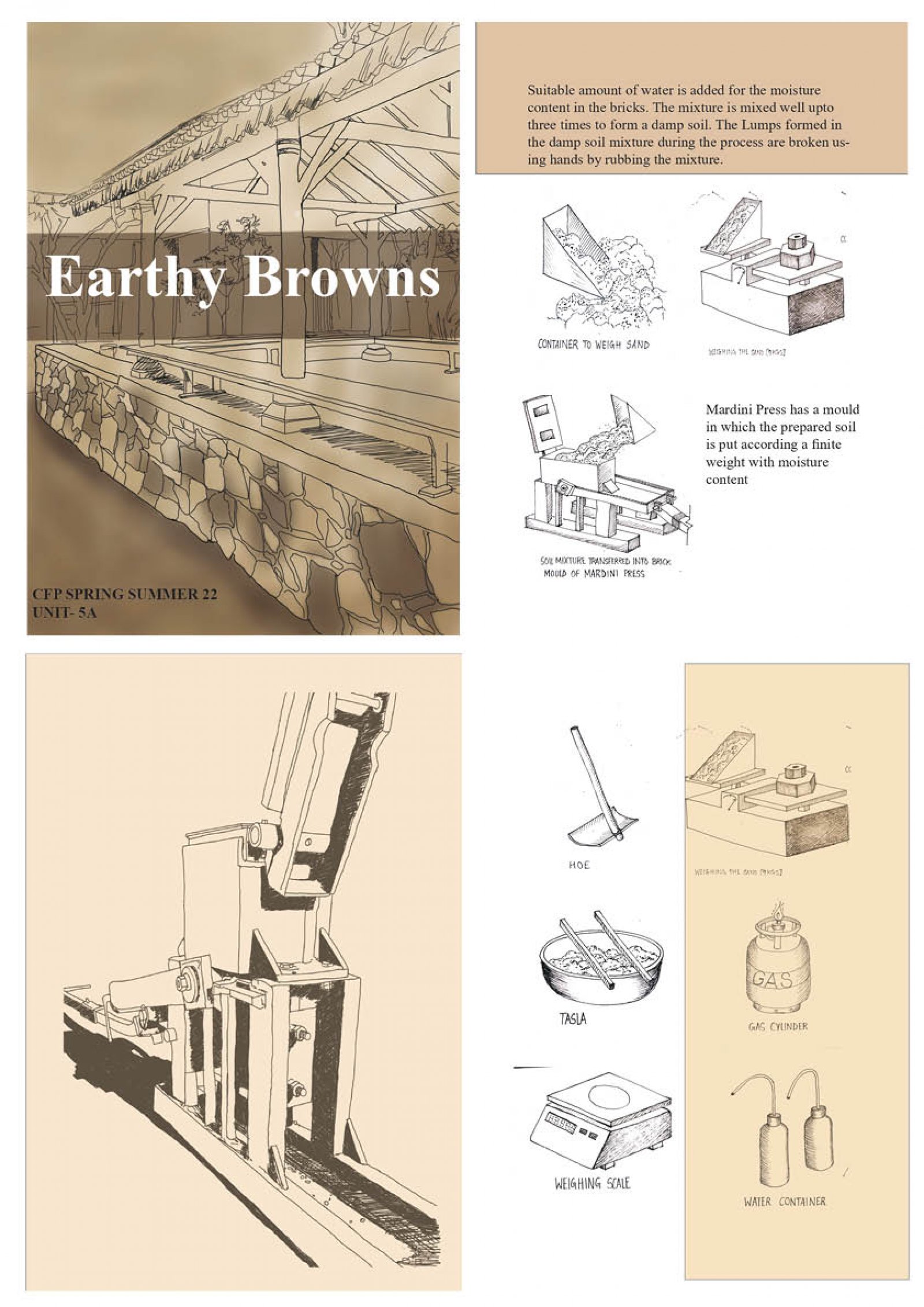
After gaining an understanding of the earth construction techniques and learning about the materials use in different places according to the weather and also learning how the foundation, plinth, dome, arch, etc can be made, we developed a booklet that has all the information we gathered from the experience we had in our learning sessions. The booklet has been divided and drafted in an understandable manner and the information is communicated with plenty of hand-drawn diagrams and digital drawings. (S14-Building Elements)

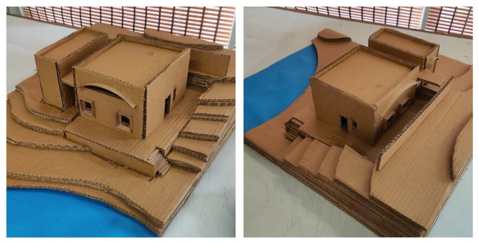
The model has been made to present the building's exterior with more elaboration and for better understanding of the placement of the building. (S17-TADP)

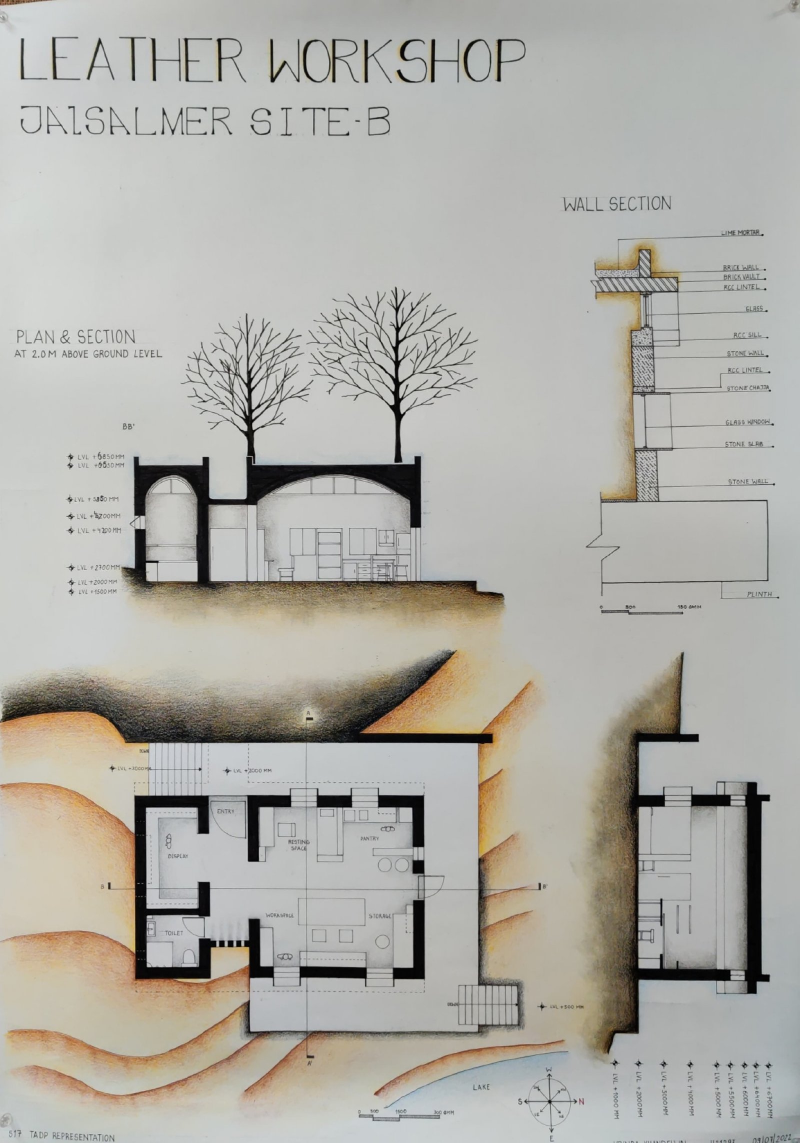
In the image above, the floor plan is on the lower left side which is showing the wall thickness and overall placement of different spaces. On above of it is a section which shows the roof in thick black filling and elevation of the interior, and on the lower right is another section with the levels mentioned. On the top right is the wall section explained in detail with labeling and hatching. (S17-TADP)

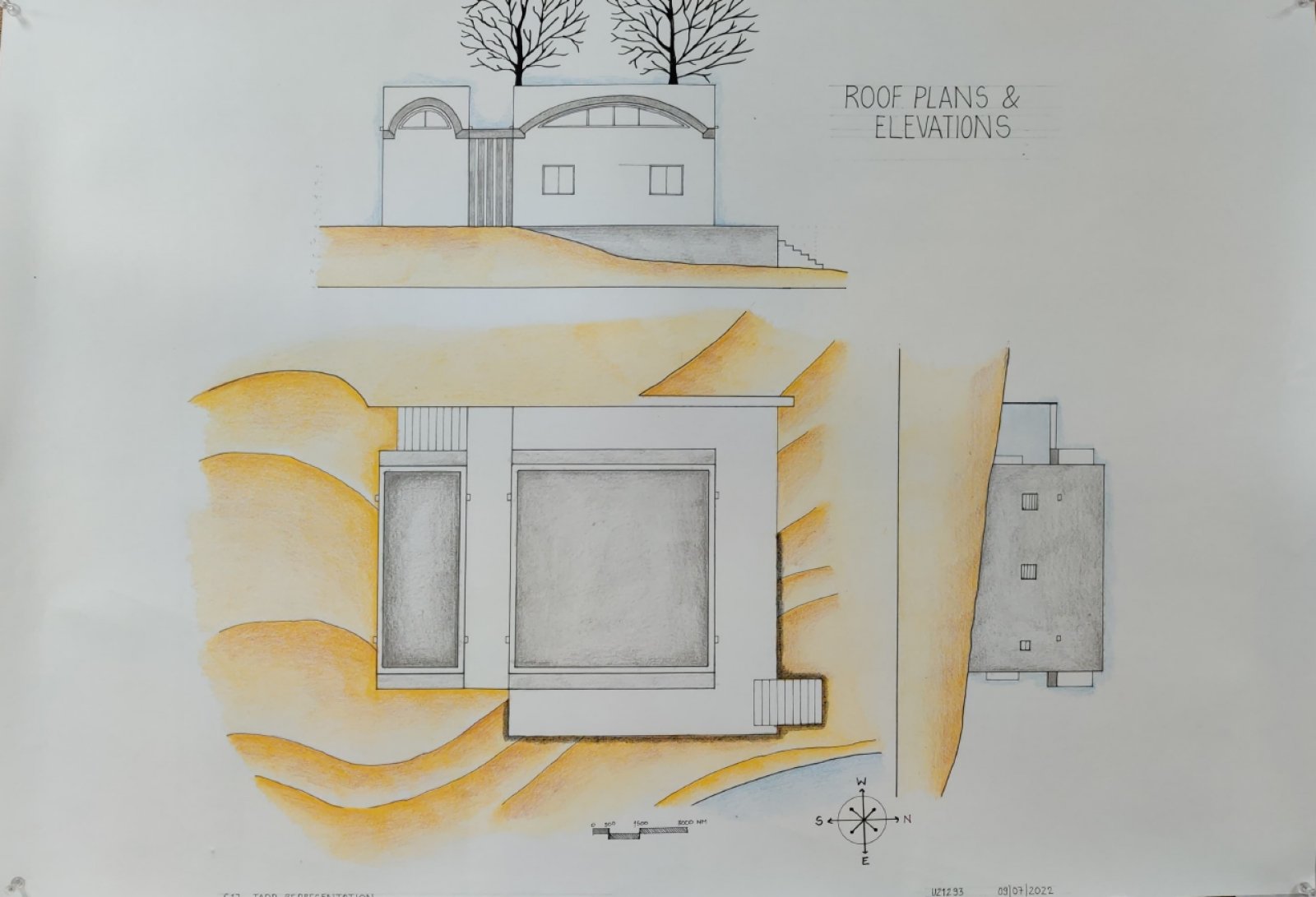
This image consists of a roof plan on the lower left and the elevations of both sides of the building have been shown on the top and on the right side of the roof plan with trees in the top elevation. (S17-TADP)

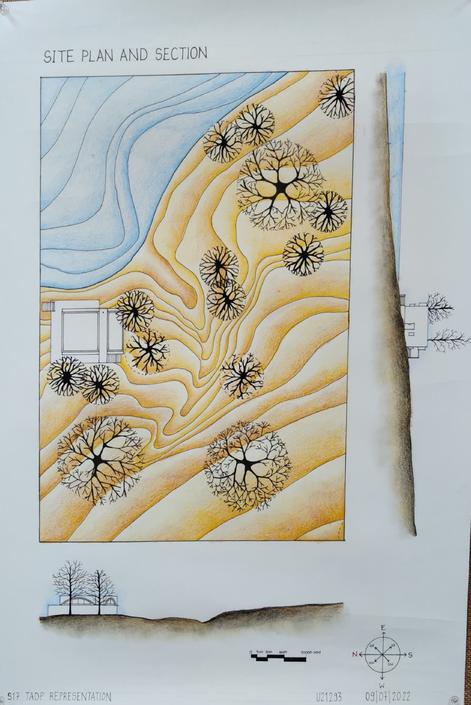
The building has been placed which is seen on the site plan shown above to get an idea of how the foliage of the trees are functioning around the building. The site plan shows the contours, trees, water body and the building's roof plan. There are two site sections seen on the lower and on the right side of the site plan which reveals the slope of the location and the elevation of the building with trees. (S17-TADP)

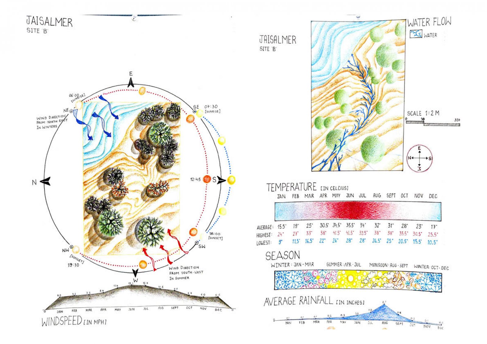
This is the study of the location which is somewhere near the lake in Jaisalmer. The study is about the topography of the site, type of flora and fauna, type of winds and their direction, sun path, etc. The scales show the average rainfall, temperature, etc throughout the year. These studies have been done to decide the most suitable place to plot the building. (S17-TADP Site Analysis)