Shradha Sharma

CFP004

U21230

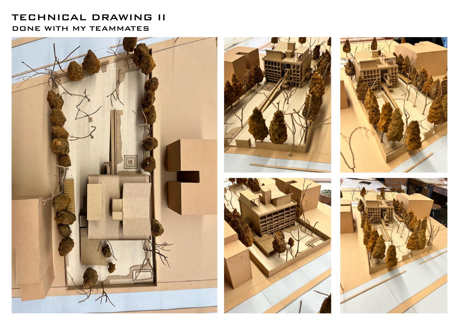
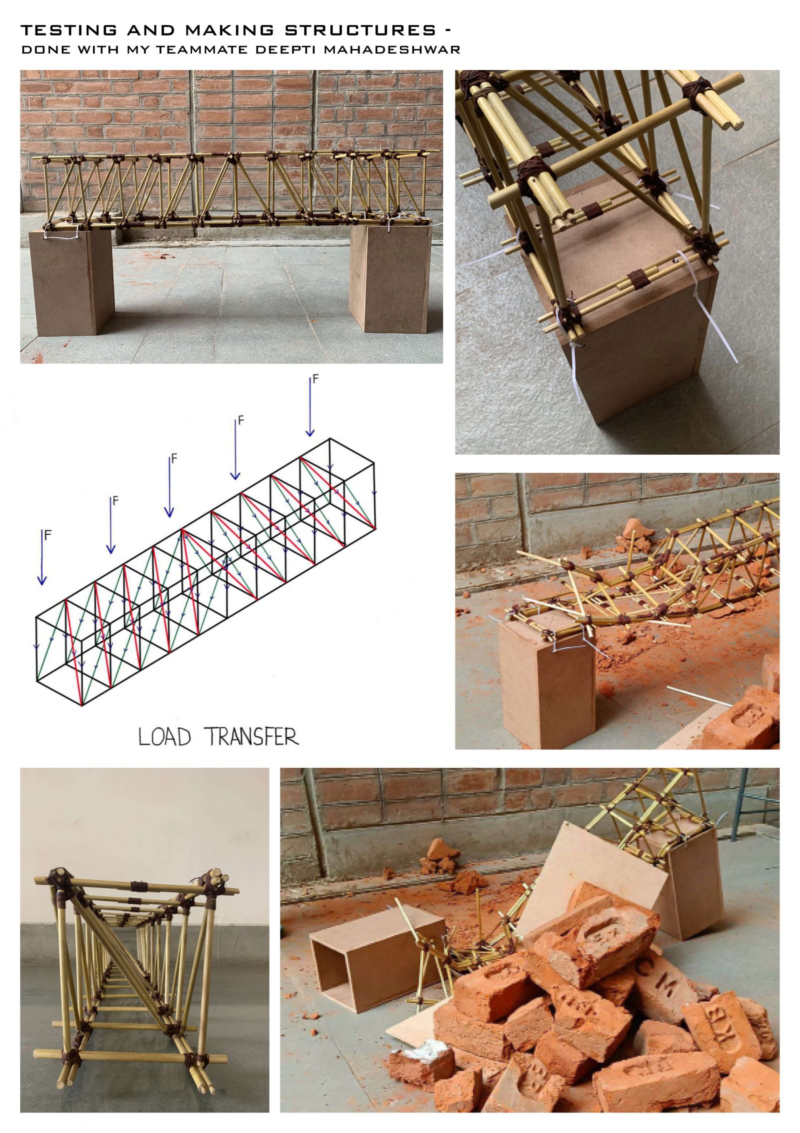
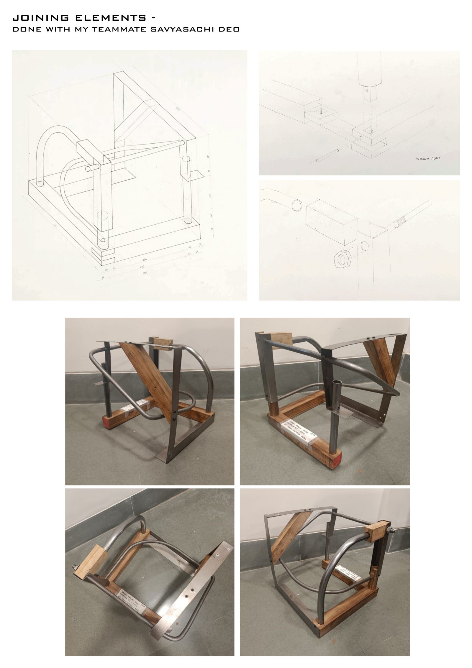
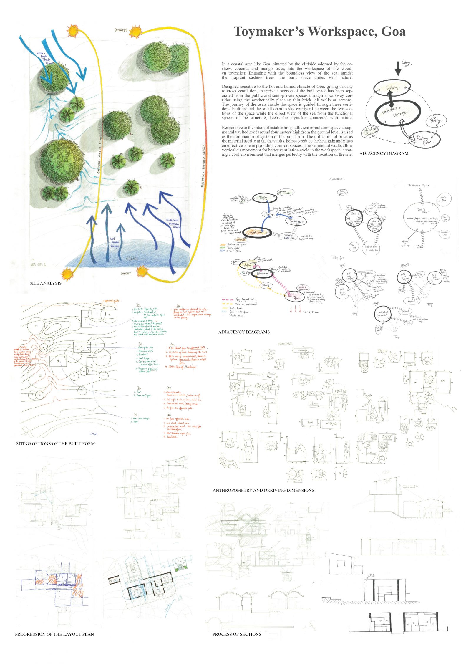
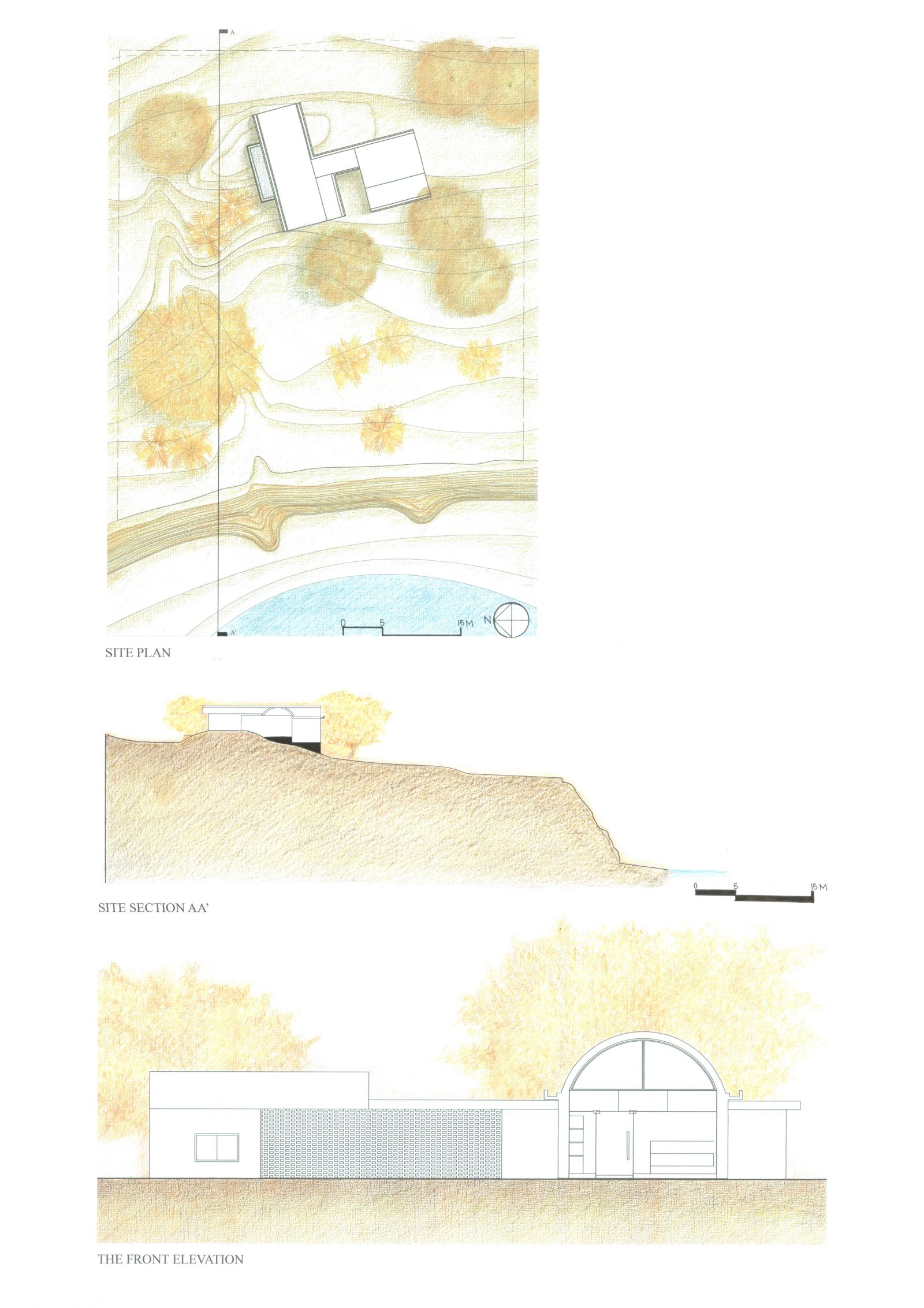
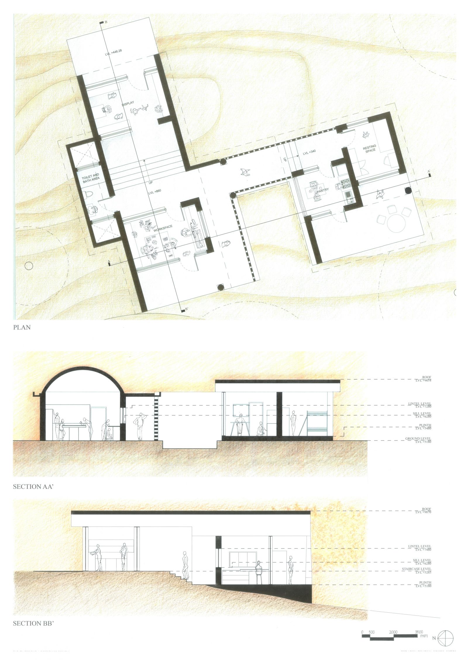
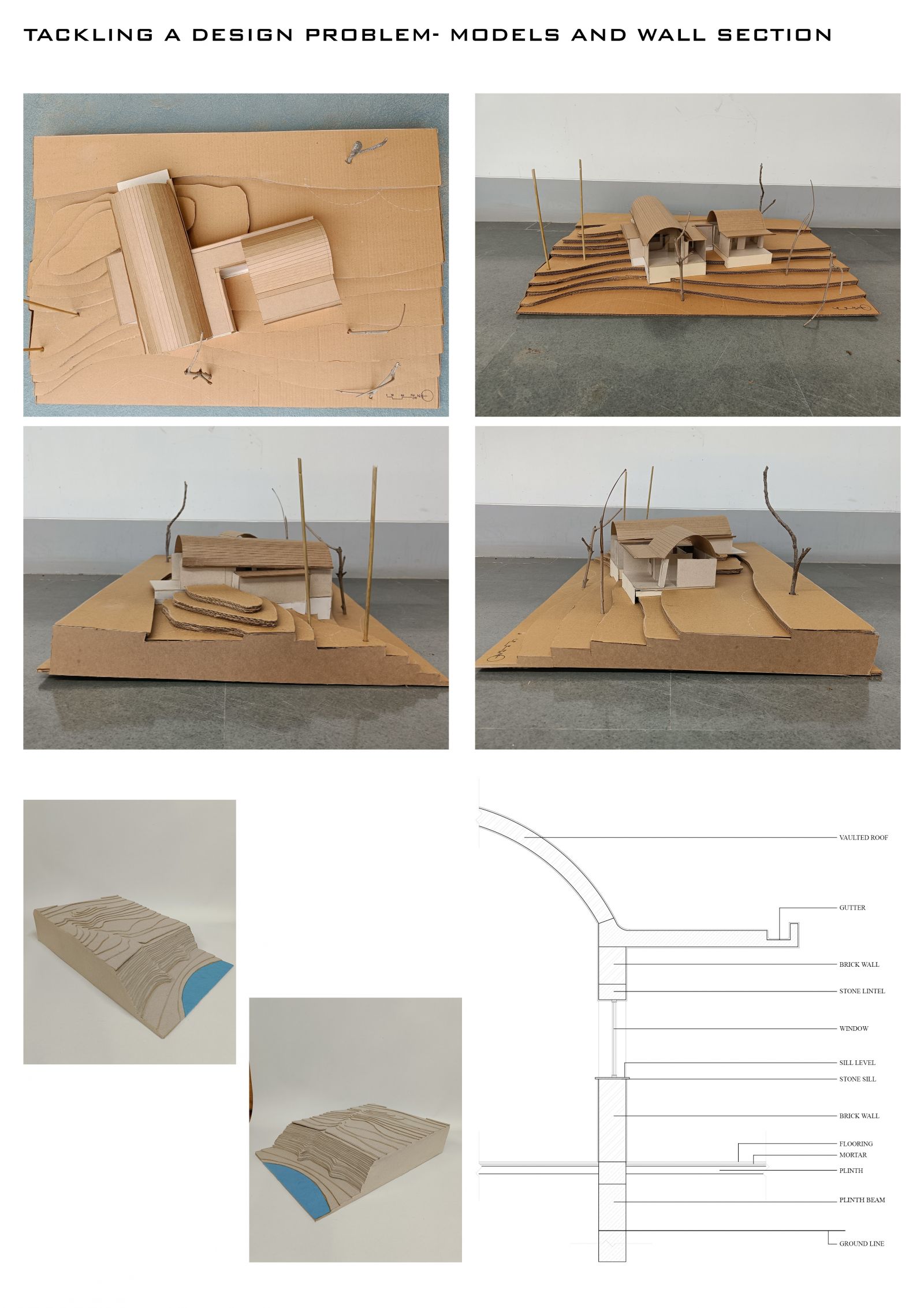
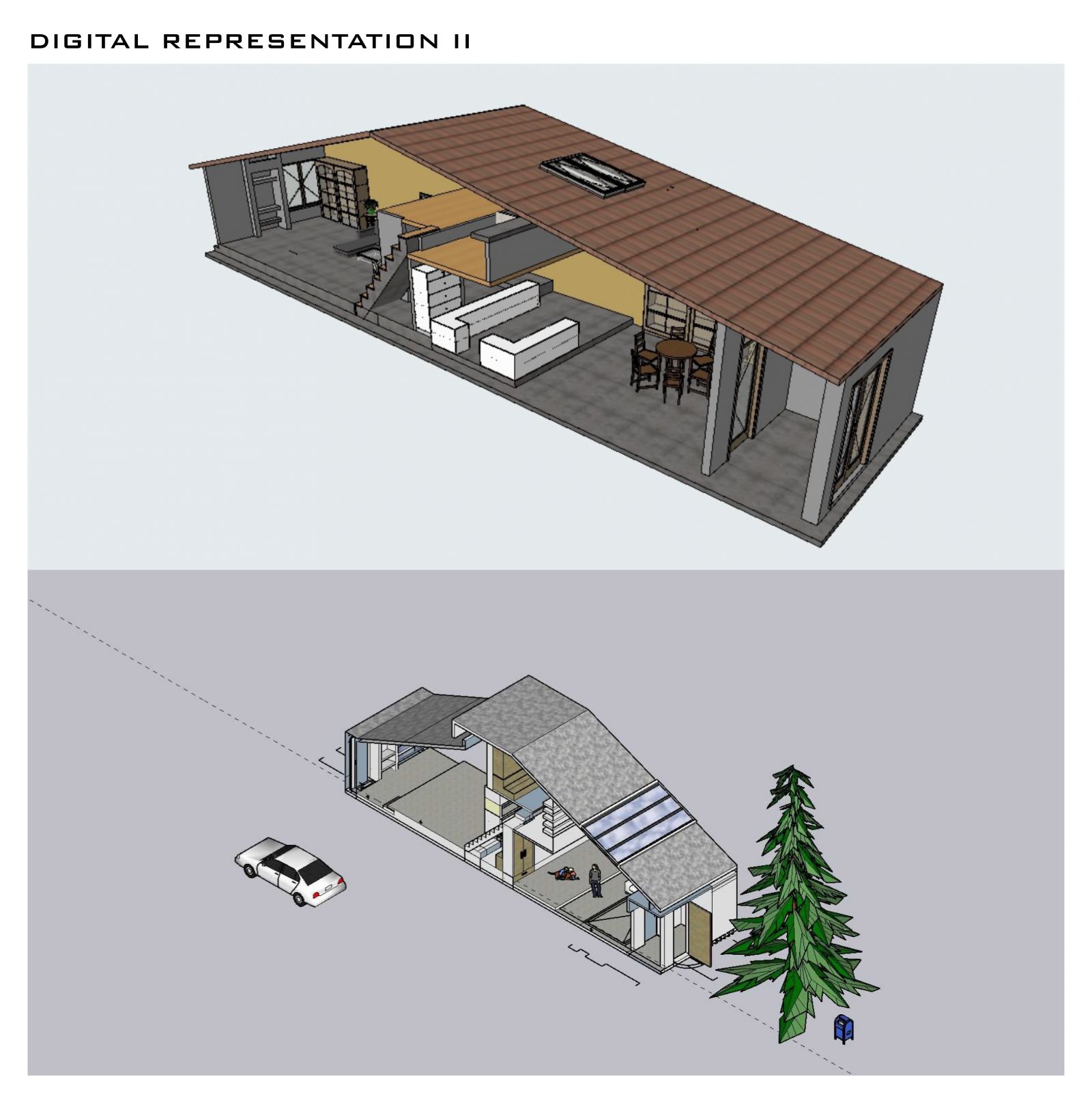
Foundation Studio (II), within the CEPT Foundation Programme continues to build upon the skills acquired during the first semester, adding abilities to use digital media in representation; to make models; to understand the assembly of built form through its building elements, materials and structures; to be able to draft architectural and topographical drawings: and eventually leads to bringing the skills and abilities together to tackle a design problem.

View Additional Work

Report Content

Display of the site model made in 1:100 scale of the ATMA House designed and built by the renowned architect Le Corbusier. The model was made by taking reference of the dummy drawings that were prepared. The drawing set was prepared in divisions consisting of plans of separate layers, elevations and sections of the site and wall sections giving in depth knowledge of the materials and method of construction.

The making and testing of a spanning member designed in the fashion of a pratt truss was done by me and my teammate to understand the type of load transfer offered by the structure. Reed sticks of various sizes are used to make the frame of the spanning member, and are bind together using a variety of lashing techniques. After the making of the structure, it was tested using bricks to determine the failure or success of the model. Member failure and bending because of the load were observed as the two factors responsible for the failure of the structure.

A 300x300x300mm cube assemblage was designed and built from scratch using a 1mm thick metal sheet, 1400mm long and 12mm thick rod, 700mm long and 19mm thick metal pipe and a wooden log of length 800mm and cross section 40x40mm. The knowledge of how different materials behave when joined together or how the physical properties of the materials effect the structure was acquired during the making process. The ideation of the structure was done in steps with the help of rough prototype models that gave clarity about the actualization of the assemblage. An isometric drawing of the final model has been shown along with some joineries used in the cube.

The sheet displays the number of steps or process that were followed to design a wooden toymaker's workspace in Goa. The intent behind my design was to merge the built form with the nature while keeping in mind the air circulation and cross ventilation in a hot and humid place like Goa. Starting with the site analysis, siting of the building was done with regards to the wind direction and sun path. Layout of the house was made after understanding the anthropometry of a human in proper scale. Multiple layouts were designed of which the final one has been displayed in the next slide.

The site plan shown at the top of the slide depicts the placing of the built form along with the roof plan of the structure. The three types of trees found in the site are differentiated by the different strokes of the pencil color. A section is cut along the site to get an understanding of the slope and how the built form uses the landform and the levels to settle on the site. Further, the front elevation of the structure has been shown.

The final layout of the built form displayed in the slide shows the some of the activities of the wooden toymaker while he resides in the form. After discussing several layouts and fixing the one similar to the final one, changes were made to the initial plan before arriving on the final result. The two sections made identify the roof and interior of the spaces while also defining the levels of different building elements from the contour line. The vaulted roof shown in section AA' not only protects the structure from the direct and harsh rays of the sun or heavy rainfall but also helps in vertical movement of air in the space giving the user an illusion of wide and open space in the small area.

The wall section shown in this slide elaborately speaks about the materials used in the construction of the built form. The model of the built form has been built in 1:50 scale, showing the details of the levels, roof and the external elements like the jali walls and stairs that are used to separate the public, semi-private and private spaces.

Drawings made during digital representation II using sketch-up and archicad respectively have been displayed in this slide.