Your browser is out-of-date!
For a richer surfing experience on our website, please update your browser. Update my browser now!
For a richer surfing experience on our website, please update your browser. Update my browser now!
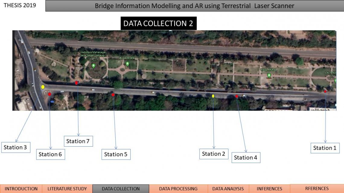
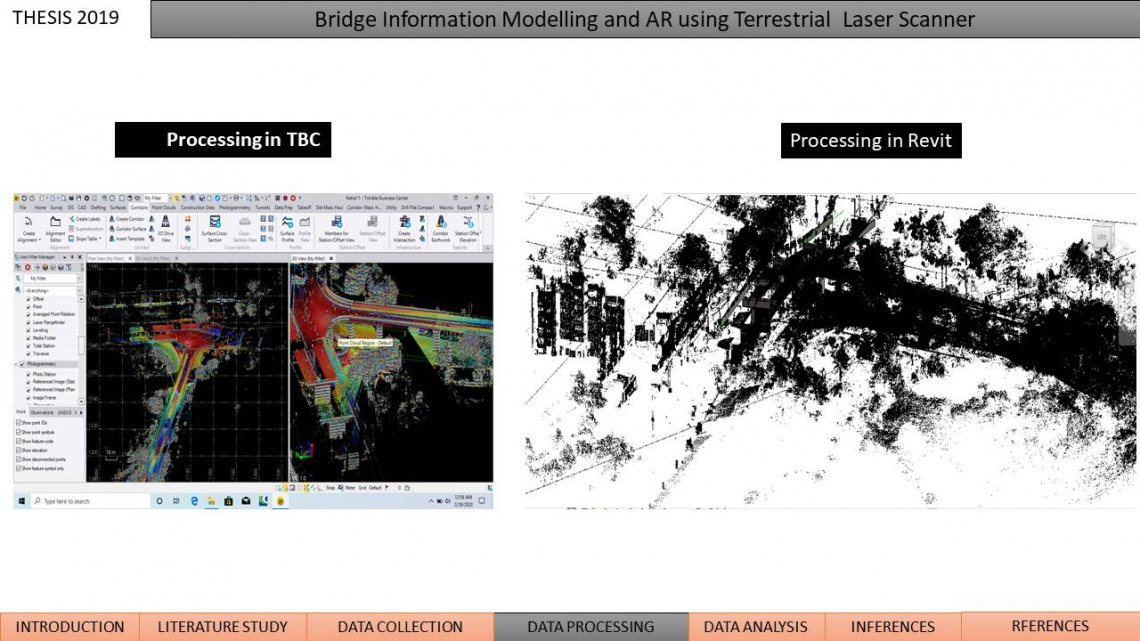
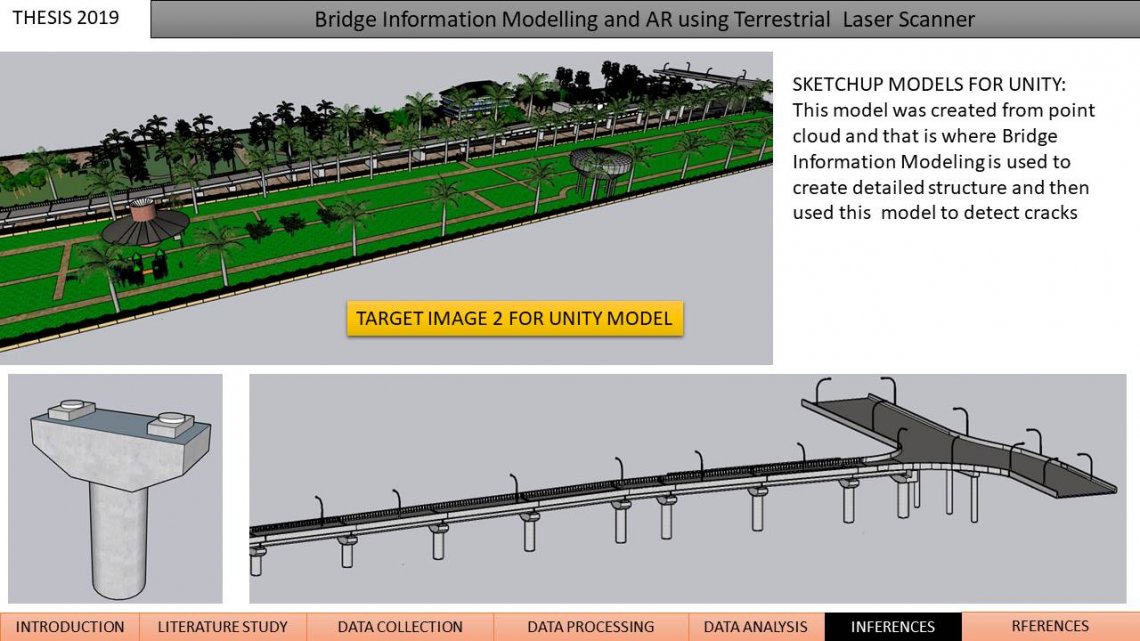
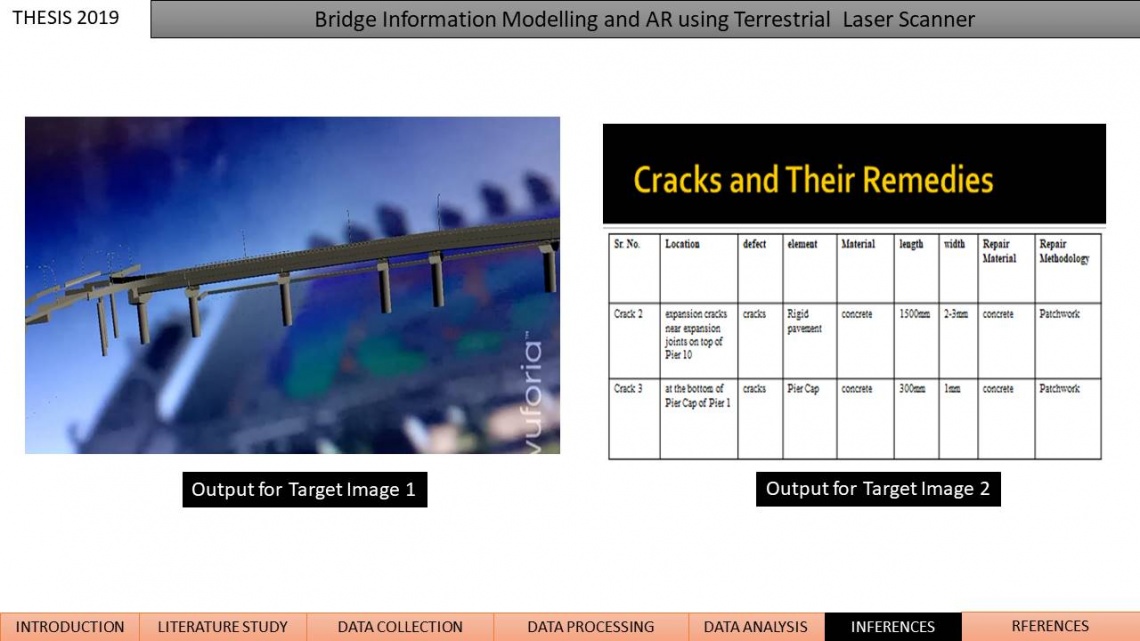
In India, there are lot of bridges getting constructed A bridge’s performance life is subjected to deterioration due to excessive usage, overloading, material aging and environmental impacts. There are various incidents of bridge failures and all this is due to lack of maintenance of bridges. There are many incidents where bridges collapse before its life span is over or just after it is built or even during construction. Visual inspection may also require rather significant logistics and bridge closure. Thus, the method is complex and time consuming when obtaining the relevant information for bridge assessment So all this call for its routine inspection and methods to do it as efficiently as possible. One of the method to do inspection is using Terrestrial Laser Scanner. The main purpose of the bridge inspection is to satisfy the public safety. Terrestrial laser scanning (TLS) is a method that rapidly and accurately acquires the 3D position information of object surfaces by contactless measurement and it produces three-dimensional (3D) coordinate information with a large number of points that describe the entire shape of a building or object. With Terrestrial Laser scanning point cloud data is obtained which is used as a base for XR technology. It’s a gaming technology.The motivation of this research is to investigate whether virtual reality (VR) could be used to address the limitations and difficulties faced by engineers when carrying out visual inspection. The scope of work includes surveying the bridge site with Terrestrial Laser Scanner. The Bridge Surveyed is Lal Baug Bridge, Vadodara. The scanned data is used to create 3-D model for the bridge in TBC and other software which can be used and then ultimately using XR technology for creating virtual bridge for Inspection. Trimble SX10 Total Station in-built laser scanner with TBC software are Used. Also Unity Platform is used to for XR. Data was collected with nine scan positions as shown in table. We used local coordinate system. STN X Y Z CODE 1 1000 1000 100 stn1 2 1032.953 1000 100.549 bs 100 1234.069 1078.176 107.158 stn2 101 1383.856 1137.359 110.873 stn3 102 1049.498 1001.592 101.78 stn4 103 1298.252 1102.227 101.189 stn5 104 1376.654 1135.819 101.786 stn6 105 1370.584 1130.801 101.522 res stn 6 106 1356.484 1138.863 101.559 stn 7 Working with Terrestrial Laser Scanner Setting up of instrument at station 1 • Centering and Levelling of the instrument is done(levelling is done with video plummet) • Marking of point • Setting up a new job and entering data like height of prism and point name in TLS controller • Locating the prism(auto-locking system) • Starting the scan-11minutes Machine is shifted to location of prism and then station 1 was backsighted by keeping prism at station 1. This data is the output of laser scanning process and then the data was processed to make the model after removing the unwanted data. The point cloud data was imported to work upon and use point cloud as base model. The output 3-D model of the bridge is as under. After this the landscaping was added to the model to make it a good model for doing XR the following image shows the crack identified and also the output of Unity is also shown. This image on left in VR Unity App will show the output as image on right side. Final output as shown below: