Your browser is out-of-date!
For a richer surfing experience on our website, please update your browser. Update my browser now!
For a richer surfing experience on our website, please update your browser. Update my browser now!
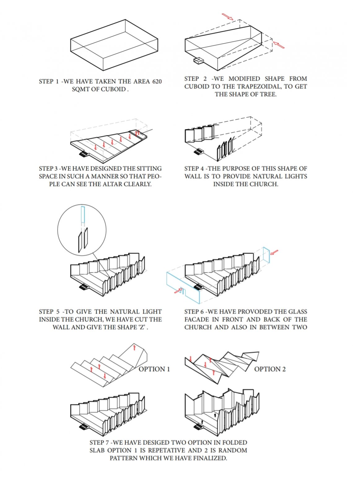
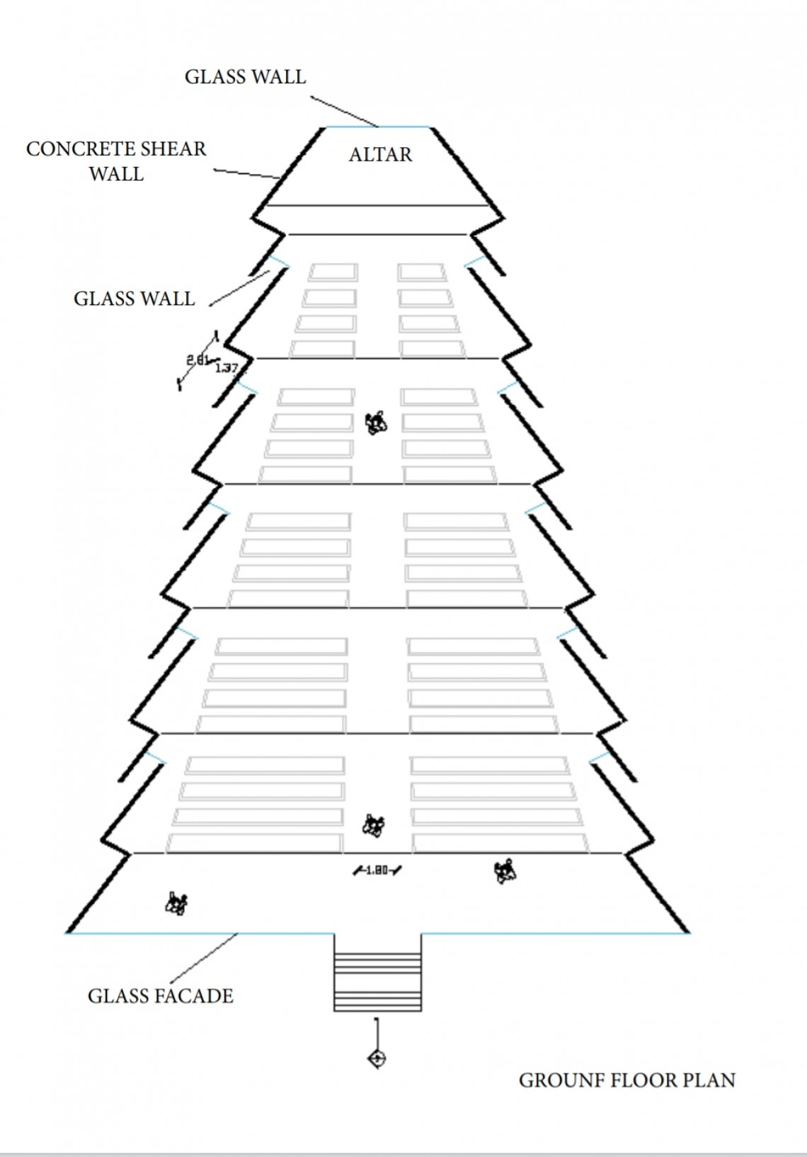
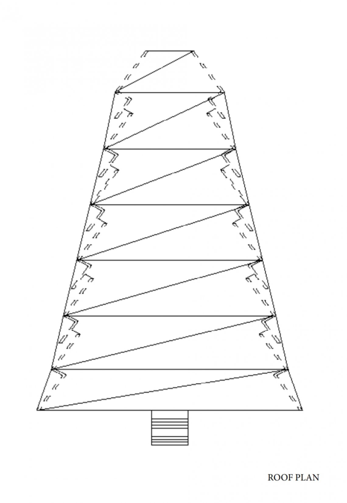
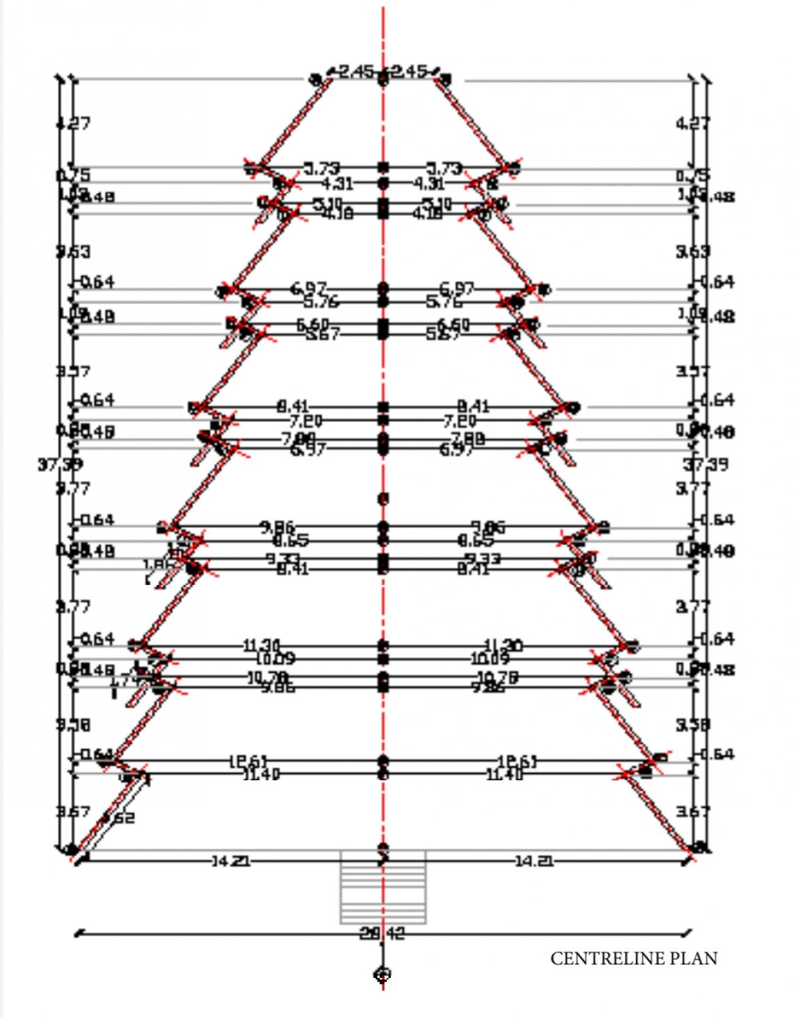
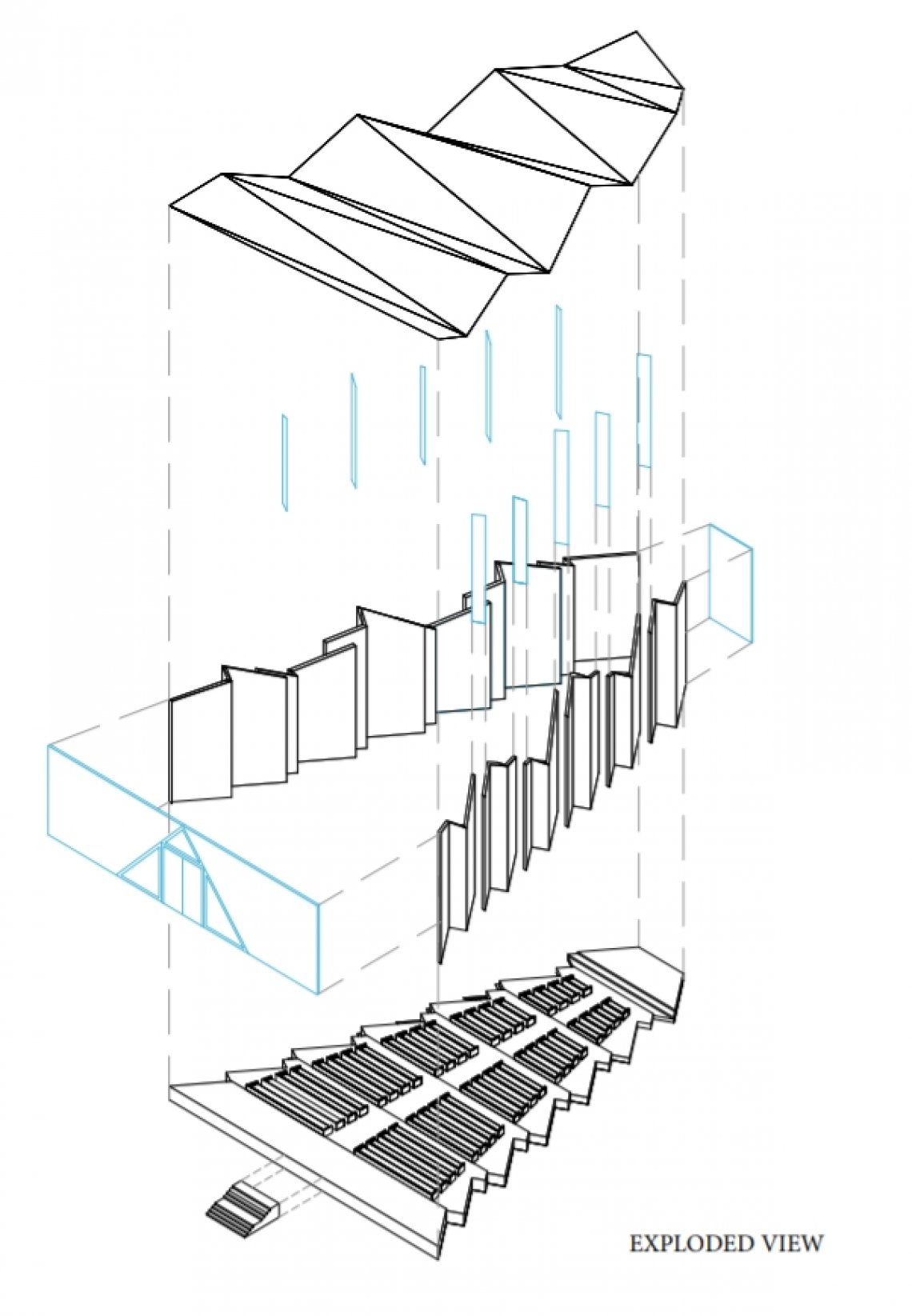
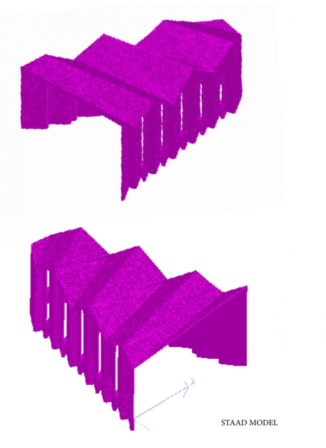
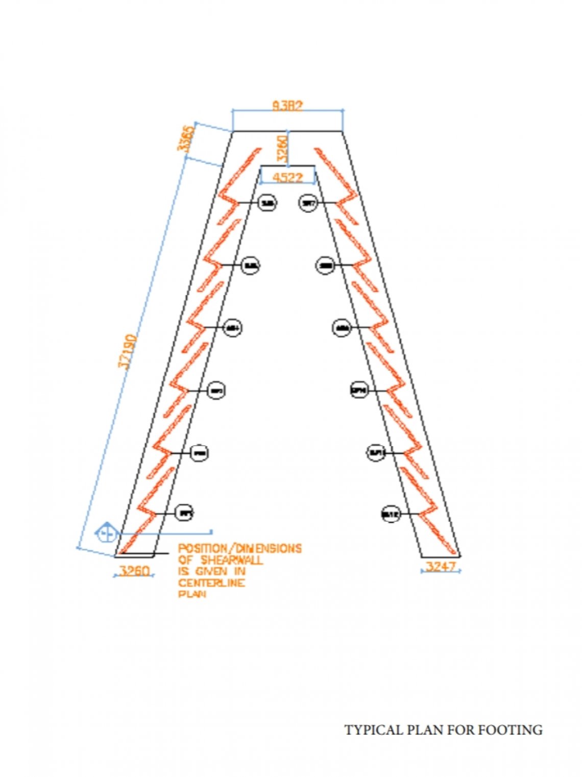
About the studio: we learn so many things about architectural as well as structural. It was great opportunity to learn these both things at a one time. From this studio we umderstood that how only RCC structures can also help us to design the space, And we also lear the designing of reinforcement & how to analyze the building. Introduction There are many structural systems, here we have given a folded plate system. - Folded concrete plates generally used for longer span and where we don't want a column in the larger area like theaters, stadium, halls etc. - So the Defination of folded plate is, assemblies of concrete plates rigidy connected together along with their edges in such a way that structural system is capable to take load without giving any supporting beam along mutual edges or any columns in between. Principal : -the pattern of the folding -basic geometric shape of system -the desigm of the bearing there are many types/ patterns of the folde It can be a slab, it can be walls or it can be slab and wal both together. Model: Here we made a model of 1:25 scale of folded plates 10m x 5m with 150mm thick slab, to understand and visualize the basic concepts of system and how loads act on Column or walls. Case studies : We did case studies to understand more about the system. We found and learn lot of new things from these case studies. Like, in mahendra raj's structures tagor hall we understood how folded walls and slab can act together effectively. And we took this as a reference in our next module.,, Architectural part: So, upto here it is about the system. After that we've given a function, any religious place. We decided to design a church. During the designing of church we thougt about the shape of building, we wanted to design something related to church ...we draw / designed many options like cross which is a shape of Christian religion. And our another option was a tree shape, which is used for celebrating festival called Christmas. As we want to design a folded slab with folded wall, we thought the shape of tree would be nice so we decided to work on the tree shaped building. Our design criteria was, we have to design a space in specif area by using the structural system which was given to us. Design of Folds: As you can see in the diagram we design two options for the folds. we finalized the 2nd option . The idea of that is we wanted to achieve a varying volume and also different heights of wall. In that there are triangular foldes which is connected together along their edges. And the other thing which is quite different is the height of the foldes as well as walls, that is also varying height. Plans: you can see the shape of building is almost like tree as we wanted. As i said above we design these walls to get the natural light inside. Centerline : Delevring the arrangement of the building Structural part: In the structural system we have a benefits of the geometry. Which hells to tranfer the loads easily and stable the building. We did the load calculations and analysis in the STAAD PRO. And design the footing accordingly. We got the value of FY( vertical force), Mu (moment ) Area by using formula : total fy (vertical force)*10%/ SBC (200) And then we calculated the Tv and Tc (where Tv < tc) which is taken from theb IS456 table 20. After these all the calculations we come up with the minimum Ast (area of steel requirment in 1m) And assumed the dia of bar and spacing as per IS456 to get the minimum Ast. Here, we have designed a footing for folded walls. Which is connected to the one continuous pedestal. Foundation depth is 2.5m Depth of the pedestal is 500mm We did all the the calculations in excel and got the values for Ast( area of stee required in 1m) From that we got the diameter of the steel bar and the spacing betweem the bars. By doing analysis and calculation in excel, we got the Ast required in 1 metere 287.35 sqmm. So now we assumed 8mm with 150mm c/c spacing. And got NOS of bar 6 For 6No. Of bar area of steel is 300 sqmm (area of 1 bar 50sqmm x NOS.) Area provided should be greater than minimum area of steel required. So here the values are satisfying. 8mm dia with 150mm c/c distance is what we provided for our reinforcement of footing. Wall below the ground level is 300mm thick and wall above the ground level is 230mm thick. The walls on the pedestal is z shaped so it will be marked from the centerline plan where we have given the position of junctions. Conclusion : At the end we come up with results that the geometric shape of the building affect much to tranfer the load and to get the stabilized building . In our case the shape of the walls and the foldes matters in structural behaviour very much. X....... Thank you. ........x