Your browser is out-of-date!
For a richer surfing experience on our website, please update your browser. Update my browser now!
For a richer surfing experience on our website, please update your browser. Update my browser now!
Through the course of the studio we learnt the basics of structural system, then
having the function in mind we designed the structure. We started by exploring the
functional requirements and accommodating them. Later, we designed elements
of the structural system considering the loads due to the structure as well as the
function. The process of the studio:
1_Development of the idea
2_Visualization of Structure and Spaces
3_Determining placement of Structural Systems
4_Designing Structural Elements
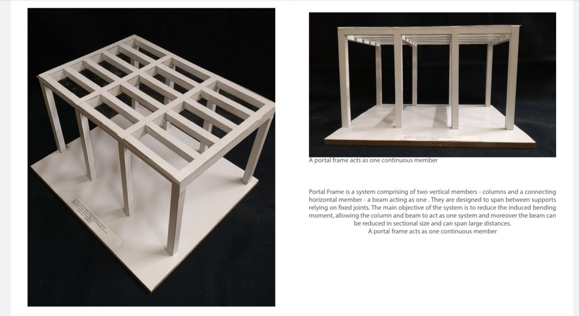
We studied the portal frames as an element, it’s basics like the span to depth ratio, general
sizing of elements, their spans and the loads they are designed for through a number of
case studies. Keeping this in mind we prepared a prototype model in 1:20 scale.
After being allocated a specific program, we did some further case studies (on the
program ) and learnt basic zoning (for example allocating 60% area for service), the
basic design and specific requirements like ( placing of car lifts / jacks, etc ).
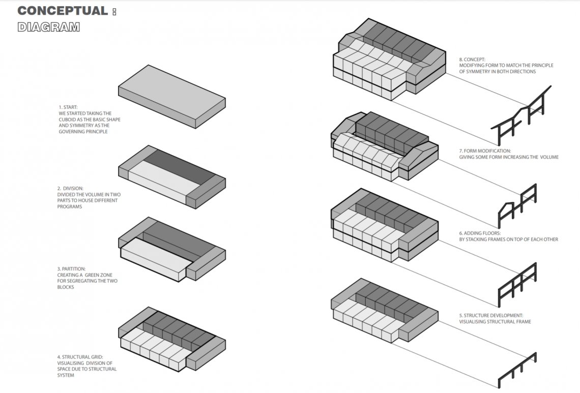
Referring the data we collected, we designed five options out of which one
was finalised. Starting from a cuboid, we reached the final design considering
functional and structural requirements.
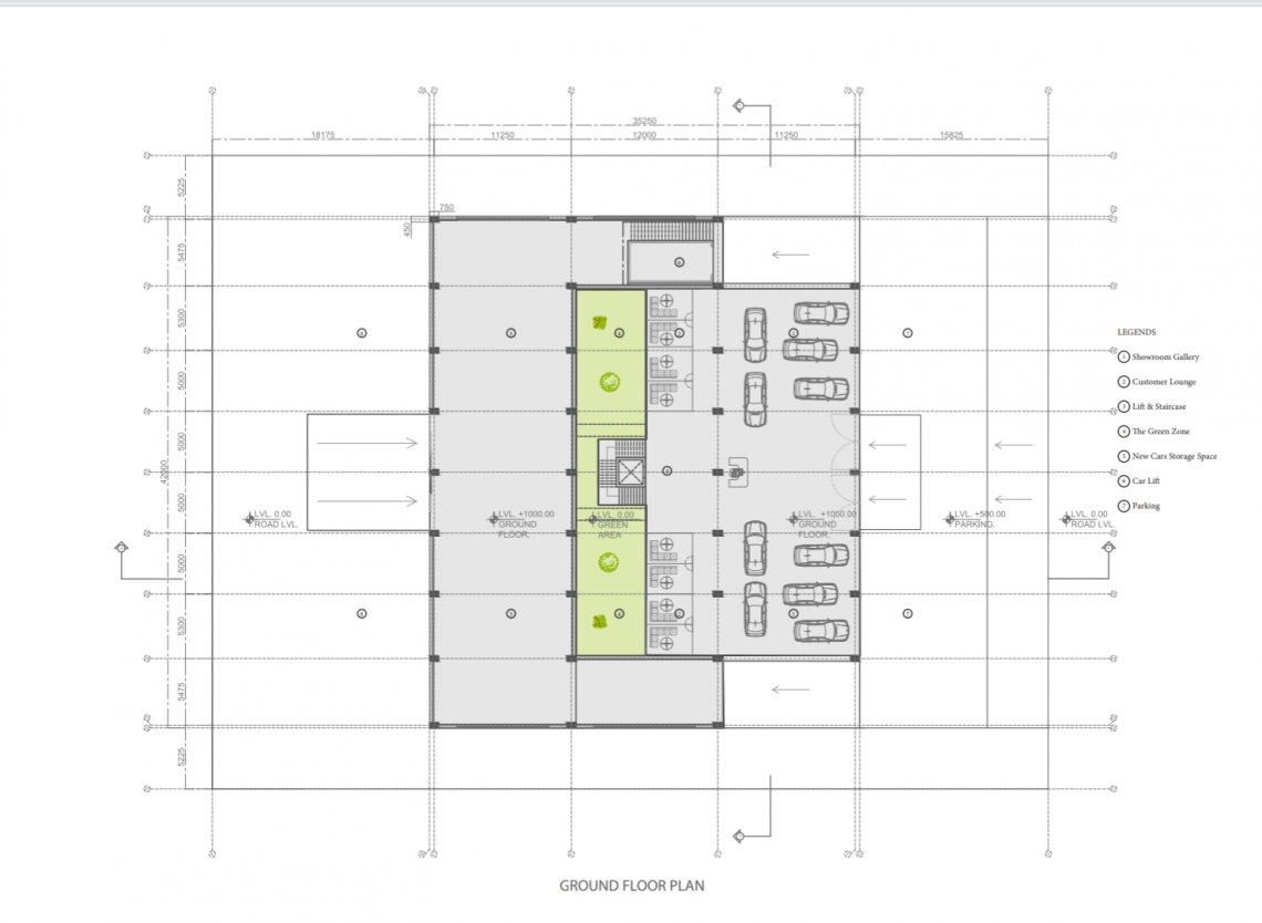
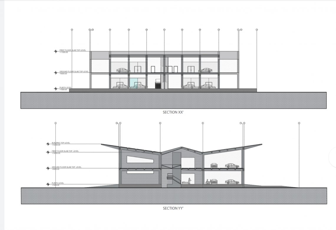
We then worked on the finalised design, allocating areas for specific purposes
and accommodating functional and structural requirements (for example the
double height space at the entrance not only gives the feeling of an enhanced
volume but doubles as a place for hoisting cars through jacks to the upper floor).
One of the principles which influenced our design was providing a circulation as
straightforward as possible.
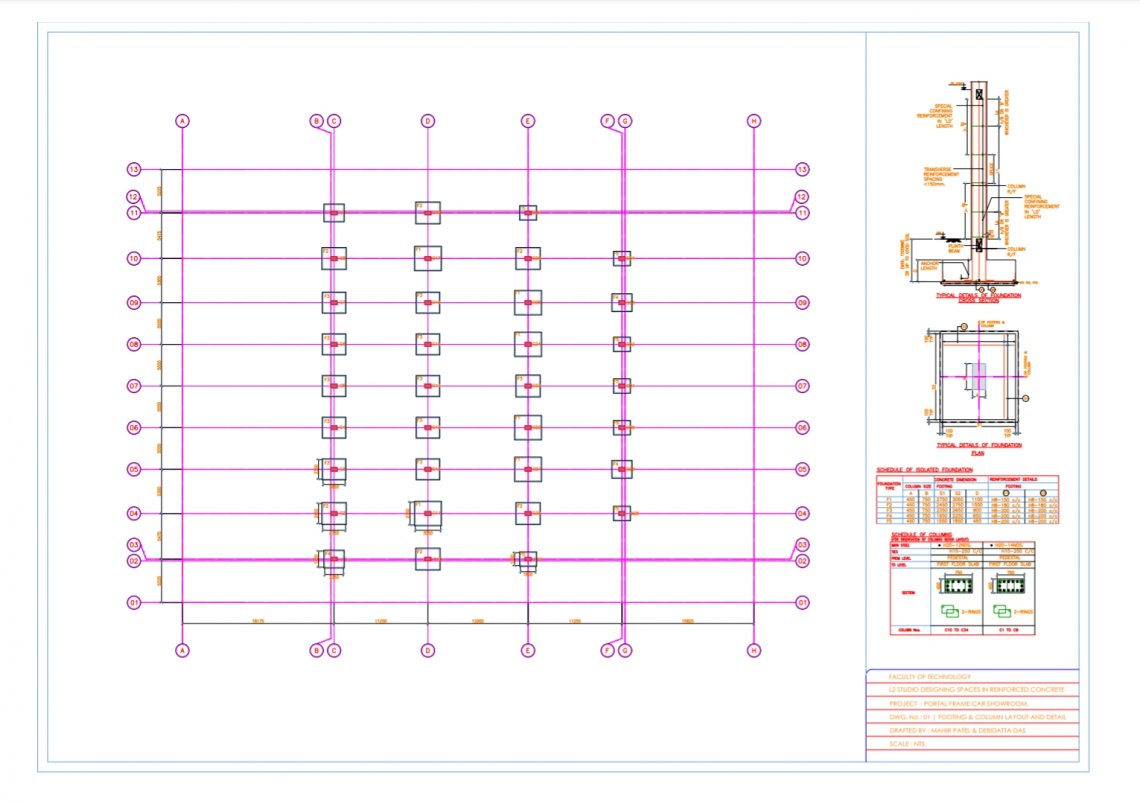
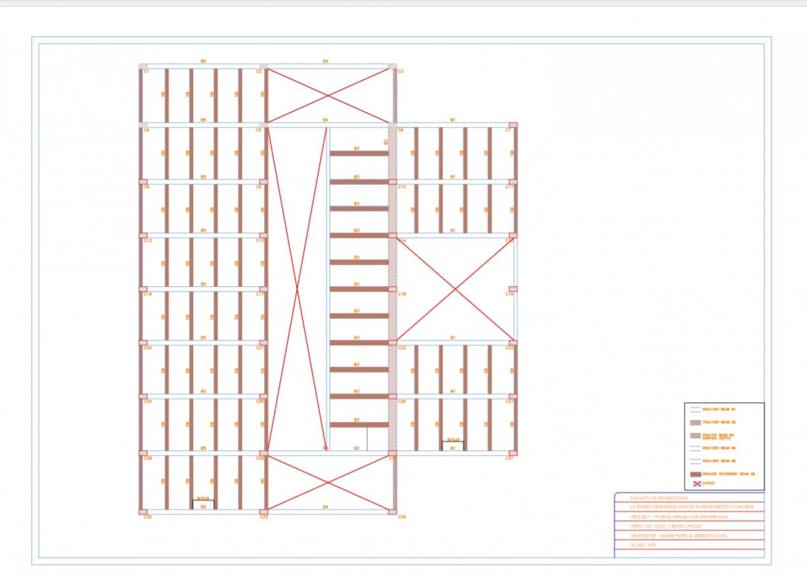
The structural system had been placed approximately, its positions were fixed and
dimensions of members were decided with respect to thumb rules. Studying the
basic load transfer we added secondary elements and decided their placing.
( The load of the slab is transferred to secondary beams, they transfer the load to the
primary beams of the portal system, further to the column who transmit it to the
underlying set of portal frames or the ground)
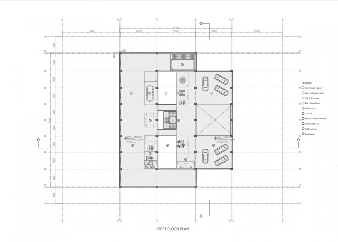
In the finalised design, the building comprised of mainly the display zone, the service
areas and then other areas are allotted for administrative work, customer lounges,
restrooms etc. With all the improvisations we created a set of drawings:
plans, sections, wall sections and a virtual model.
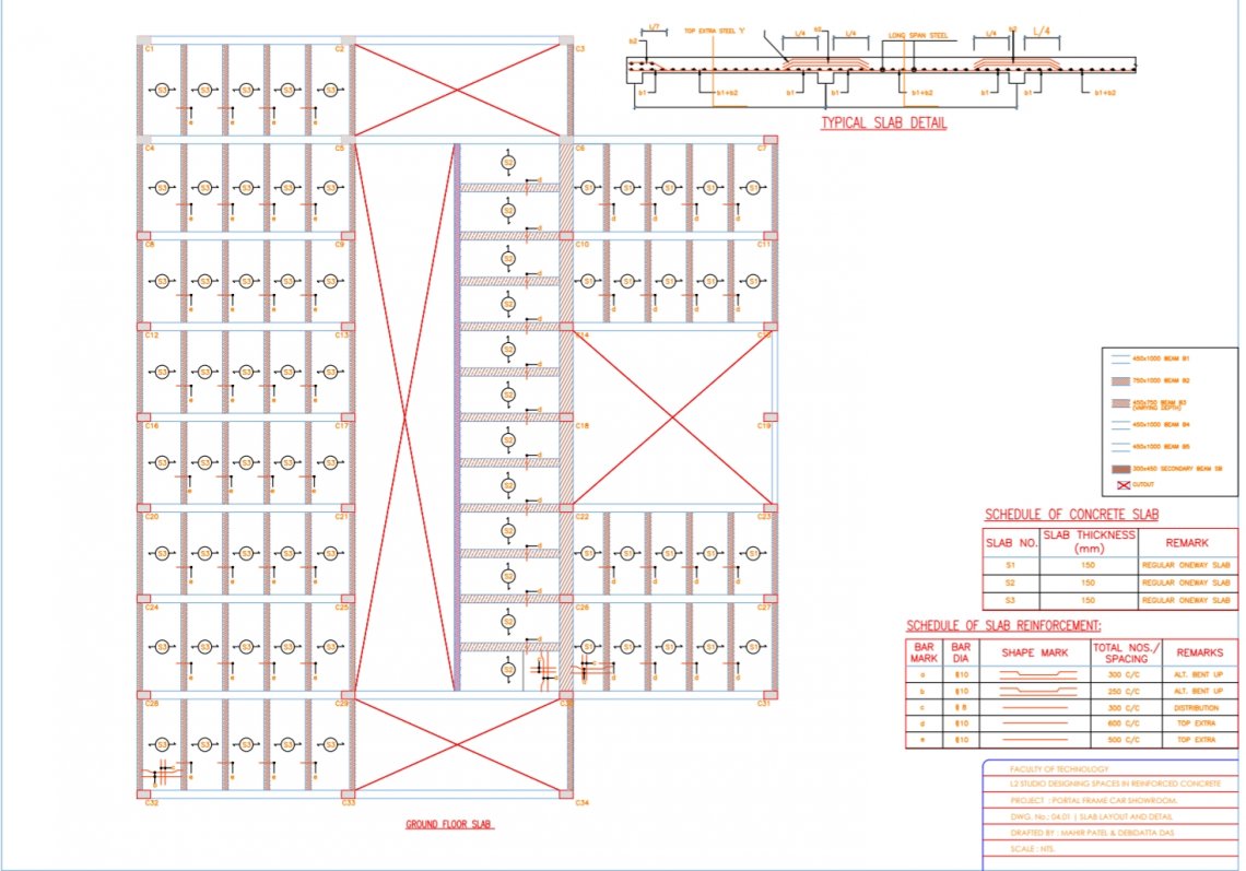
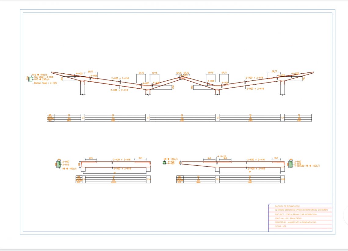
After finalisation of the design, we studied the analysis of various elements like columns,
beams and slabs ( their ability to resist moment and their behaviour under various
loading conditions) and analysing them. We learnt how to design an element; providing
it’s dimensions, it’s reinforcement, and a suitable combination of both to resist the loads
acting on it.
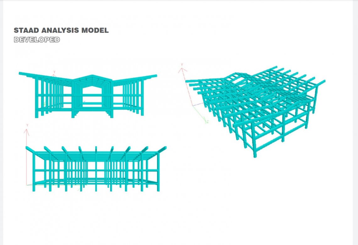
The structure was then modelled in Staad Pro, the dimensions of the elements which
we had previously provided were considered for the time being. We assigned loads to
elements referring to the IS codes according to the loads acting on them ( dead and
live). Taking values of loads and moments acting on an element from the software, we did
analysis of the elements and for any element that failed in a given aspect under the loads
acting on it , necessary steps (modified their dimensions or increased/ decreased their
assumed reinforcement) and worked out their final design.
link to Portfolio https://drive.google.com/file/d/1TQI9DnAP6qLP_3owOlnwYWcWcCmvsBIN/view?usp=drivesdk
link to walk through https://drive.google.com/file/d/1wOOxQcfWhzkeKZ82DEDg-M2-elrnYW50/view?usp=drivesdk